
Define the object and the release decision
A bare board, a populated PCB and a completed semiconductor probe card can all contain electrical connections that need testing. They present different access, handling and measurement problems. Before comparing tester names, write down the object arriving at the station and the decision that must follow a pass or a failure. Include where the result goes next and who can approve a retest. This gives the equipment trial a practical purpose.
For a bare board, begin with the connectivity and isolation requirements associated with the manufacturing data. For a probe card, separate the MLO and PCB before assembly from the later populated and completed stages. The final interconnection may include intentional resistance or components that affect interpretation. A test programme needs those facts before it can assign a useful pass limit.
Check access with the fixture installed
Provide the panel or card outline, thickness, mass, stiffeners and projecting connectors. Mark the electrical targets and the areas that probes must avoid. Ask for a drawing of the loaded setup, including the insertion path and access to both faces. A published board-size capacity cannot answer whether the actual fixture obstructs a connection.
During a demonstration, use material that represents the most difficult support case. Thin or flexible panels may need a particular support method. Large heavy cards may require an option or fixture beyond the nominal test area. Record the support and clamping positions so the measured result can be reproduced after delivery. Inspect the sample for contact marks using an agreed method before approving the contact strategy.
Specify measurement separately from vision
Define continuity, isolation and any Kelvin, capacitance or other electrical tests using the applicable product requirements. Ask the supplier to identify the included measurement resources and any extra hardware or software. Agree how intentional resistive paths and embedded elements are represented. The programme and its limits should be controlled together.
Camera resolution helps describe imaging capability, while registration, probe contact and measurement accuracy each need their own evidence. Avoid converting a small optical-resolution number into a probing tolerance. Use a sample with the relevant feature size and suitable electrical references. Repeat loading and the chosen measurement sequence where that repetition is part of the acceptance requirement.
Compare the two retained platform applications
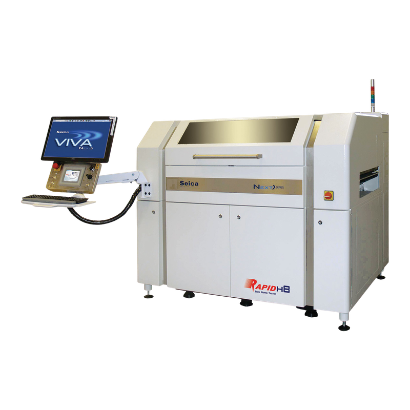
The reviewed Rapid H8A listing describes horizontal, double-sided bare-board testing with eight independent probes. Its listed vacuum-table option is relevant to a support discussion. Ask which machine revision and loading mode the offer covers because the supplier page also refers to the H8 Next series.
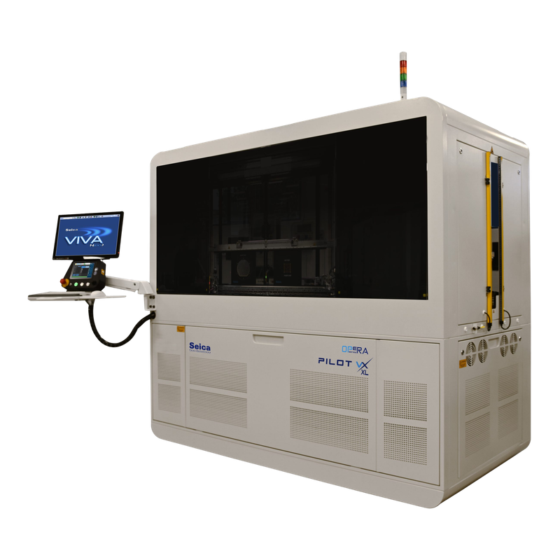
Seica describes Pilot VX XL HR for testing probe cards across several assembly stages. Its vertical XL structure addresses larger boards, with optional thickness accommodation. That makes dimensions, fixture design and final interconnection testing central questions. These platform descriptions help choose an evaluation route. The actual sample, required tests and offered configuration must decide the purchase.
Build an acceptance trial that can reveal a failure
Agree a representative good sample, known defects and suitable reference measurements before the demonstration. Record the data file, programme version, probe configuration, fixture and thresholds. Show the complete sequence from registration through test and final result. A useful trial includes the expected detection of a fault, so the team can evaluate both coverage and reporting.
Measure the full panel or card cycle. Loading, programme preparation, registration, measurements, retries and unloading all consume capacity. Keep single-cycle time separate from sustained accepted output. For mixed batches, demonstrate a normal changeover and check how the operator selects the correct programme. Ask what happens to a failed item and how its earlier result remains linked during review and retest.
Keep the evidence useful after installation
The handover package should identify software rights, service responsibilities, calibration evidence, fixture drawings and replaceable probe references. Request the settings and reference samples used during acceptance. For used equipment, check computer, controller or motion replacements and confirm that the offered software can import the required data and export usable results.
After transport, run the agreed installation and measurement checks before relying on production results. Keep changes to probes, fixtures and programmes traceable. An unexpected reading can originate in the product, contact path or measurement setup, so the troubleshooting record should preserve the conditions needed to distinguish them. Exact service intervals and electrical safety procedures come from the corresponding equipment instructions.
Technical Sources
The trial framework is procurement guidance. Apply the product specification and the selected tester instructions to set the actual limits.