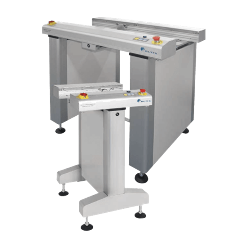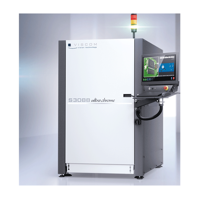

A mixed-model SMT line needs a controlled handoff between machines and inspection feedback that reaches the right operator at the right time. The current batch covers both sides: PCB linking and transport equipment, plus 3D AOI. Together they define how boards arrive, how they are identified and when a defect signal interrupts normal flow.
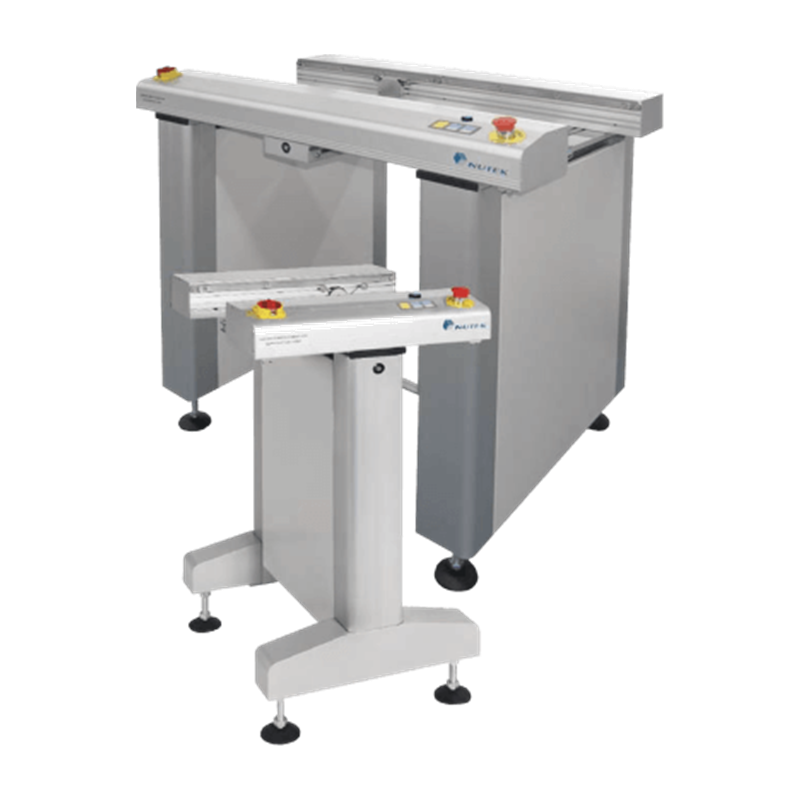
Physical handoff
Keep board movement predictable
- Define the transfer direction, board range, rail height, stop position and handshake for every connection between process machines.
- Use buffering intentionally: it can protect a downstream process from a short interruption, but it cannot correct a persistent line-balance problem.
- During changeover, confirm that the selected board width and program are aligned before boards move into inspection.
Inspection feedback
Use 3D AOI as a closed-loop decision point
Set the inspection program, defect criteria and acceptable disposition before the first board arrives.
Define what happens to a flagged board: stop, buffer, route for verification or continue under an approved rule.
Confirm that the real installed camera, software, conveyor and verification configuration matches the proposed work.
Review false-call recovery and rework loops with actual boards, not only a published inspection-speed figure.
Practical actions
Plan the line as one system
- Document the current batch's transport and inspection categories together with the upstream and downstream process positions.
- Ask for a demonstrated board transfer, sensor response, stop accuracy and inspection cycle using a representative product.
- Keep a clear escalation route for boards held by inspection so operators do not create an uncontrolled queue at the conveyor.
Avoid these mistakes
Common integration mistakes
- Treating a conveyor as passive hardware without confirming the actual interface and board-handling settings.
- Buying inspection capability without defining the reaction to a flagged board.
- Using family-level specifications as proof of the installed configuration or the throughput of a used unit.
Applicability limits
Validate the offered configuration
This review connects current batch categories; it is not a production promise. Board geometry, product mix, data interfaces, program maturity, operator response, installed options and machine condition determine the practical result. Verify each offered unit with model, serial, configuration and running evidence before quotation or release.
Technical sources
Nutek Europe: PCB conveyor context