
Buffer configuration
Measure both sides and the support plane
Supply the board outline and the maximum permitted component heights above and below its support plane. Include tolerances, fixtures and any projecting connectors. Ask the supplier to overlay this envelope on the rack drawing. A component-height figure without a reference plane can be misunderstood. The high-component buffer reference is a separate configuration lead; the pictured VB-460XL is handling context and must not be relabelled as that chassis.
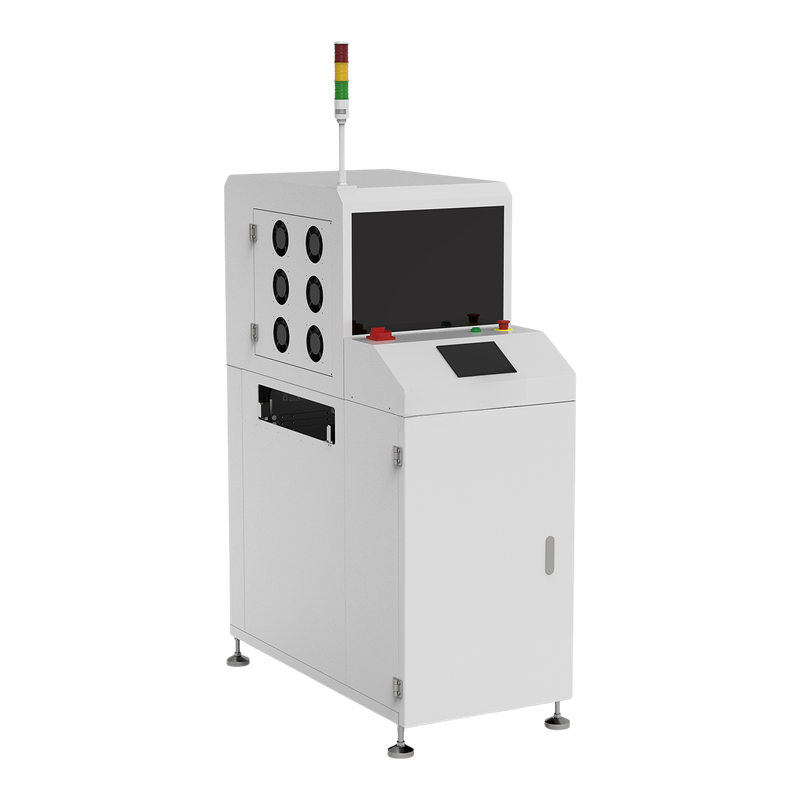
Buffer configuration
Count only positions compatible with the assembly
Ask which rack positions may be occupied simultaneously by the tallest assembly. Clarify whether wider pitch, omitted positions or a different support arrangement is required. A nominal slot count describes the reference arrangement, while useful capacity is product-specific. Include the board immediately above and below the test assembly. Demonstrating one board alone cannot establish clearance when the rack is populated.
Buffer configuration
Inspect clearance throughout the storage cycle
Under the approved commissioning procedure, observe entry, indexing, waiting and discharge with representative populated boards. Check the support during movement, rather than only at a stationary slot. Agree the intended release order and confirm board identities after a pause. Listen or look for contact evidence through the supplier-approved observation method; do not reach into or bypass a guarded motion area.
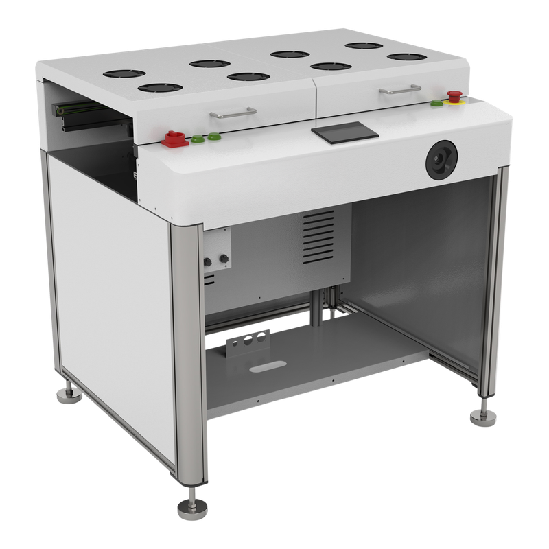
Buffer configuration
Quote the rack and capacity together
Put the rack drawing, permitted assembly envelope and usable position count in the purchasing specification. Request the exact controller mode and any changed pitch settings. Capacity accepted for this configuration should not be transferred to another assembly or rack. On a used unit, inspect the actual supports, lift hardware and sensors instead of relying on a clean model-reference illustration.
Technical Sources
Reference functions and configuration boundaries
The manufacturer references below support the equipment examples. The purchasing questions are an editorial decision framework, not measured LCSMT results or a machine-specific acceptance limit.