
Buyer decision 1
Start with usable board positions
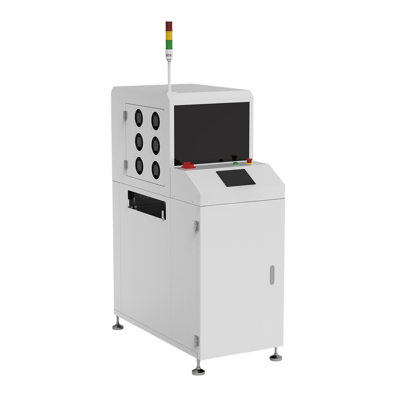
A vertical buffer can absorb a temporary downstream interruption, but its nominal slot count is not automatically usable for every assembly. Component height, support spacing and the installed rack determine which positions can be occupied. The Vanstron VB-460XL reference table lists twenty positions and a twenty-five millimeter spacing. Do not assume every tall assembly can use all twenty. Obtain the rack arrangement and trial the tallest populated board on both sides. The VB-460XL image is a manufacturer model reference, rather than a witnessed capacity trial.
Buyer decision 2
Convert free positions into an interruption allowance
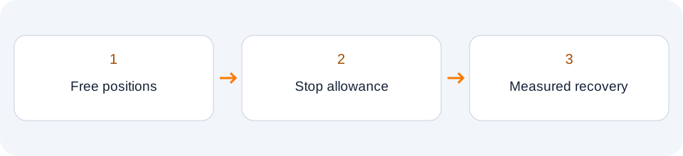
Use the arrival interval and the number of genuinely free positions at the moment the interruption begins. As an illustrative planning calculation, twelve free positions with one arriving board every ten seconds provide about one hundred twenty seconds of additional arrivals, before allowance for boards already in transfer. This is not a specification for any model. Confirm the starting occupancy and subtract positions that cannot be used by the assembly. A partially filled buffer buys less time than an empty one, even when its nameplate capacity is unchanged.
Buyer decision 3
Check that the queue can actually drain
After the downstream machine restarts, compare arrival rate with sustained departure rate. If one board still arrives every ten seconds but departure also takes ten seconds, the accumulated queue does not shrink. With an illustrative departure interval of eight seconds, the difference in rates is only one board per forty seconds. Clearing ten queued boards would therefore take about four hundred seconds under those steady conditions. Real operation may include exchange delays and changing cycle times. Use measured line behavior for sizing rather than presenting this simple example as guaranteed performance.
Buyer decision 4
Agree FIFO, LIFO and bypass behavior
FIFO, LIFO and bypass serve different material-flow needs. Decide which mode the product requires and document whether a board can overtake another during storage, bypass or operator intervention. Number a trial sequence, interrupt the output and inspect the order released after recovery. Keep board identity with the selected mode. If inspection decisions or traceability depend on the original order, a last-in-first-out sequence may need a different downstream association method. A brochure listing several modes does not establish the default or installed controller implementation.

Buyer decision 5
Test the full-buffer boundary and restart
Fill the agreed usable positions under a supervised plan and record where the next approaching board is held. Check upstream inhibition and the full-buffer indication. Document operator access and recovery according to the manufacturer procedure; never bypass a safety interlock to create a test. For a controlled interruption of power or communication, inventory the boards and preserve their identifiers before and after. An apparently successful running clip can hide a controller that loses its occupied-position record. Request the actual rack condition, sensors and lift movement evidence.
Buyer decision 6
Separate storage, cooling and production capacity
Additional dwell in a buffer may provide time for cooling, but it does not prove an outlet temperature or a cooling-fan configuration. Likewise, storage capacity does not increase the sustained capacity of a slower downstream process. Use a buffer to manage an agreed disturbance profile, then address a persistent line imbalance separately. The buying pack should contain assembly height, free-position calculation, expected interruption duration, release order and measured recovery evidence. Final acceptance applies to that installed rack and tested assembly, not every product that fits the external cabinet.
Technical Sources
Published context and applicability
Source-backed model examples support this buyer framework. No LCSMT field test, offered-unit result or stock is asserted.