
Handling interfaces
Turn the board outline into a contact drawing
Supply the released board outline with its revision and identify the edge intended to run on each rail. Mark connectors, breakaway tabs, cutouts and components close to those edges. Add separate upper and lower component envelopes. A maximum length and width pair leaves these contact details unanswered. Ask the supplier to return the proposed support surfaces on your drawing, so the drawing becomes an agreed interface rather than an informal attachment.
Handling interfaces
Do not equate rail support with usable clearance
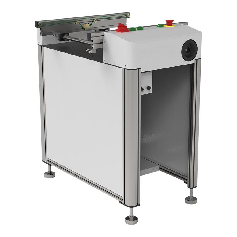
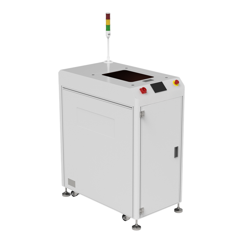
The linking conveyor and flipper references describe different transport duties. Their published edge-support fields are useful starting points, but they do not establish clearance for your assembly throughout every movement. Request a section view showing belts, guides, sensors and any clamp. For a flipper, include the swept envelope during inversion. An unobstructed straight transfer proves less than an unobstructed complete handling sequence.
Handling interfaces
Choose samples by contact difficulty
Select a sample with the smallest allowed edge margin, another with the tallest underside population and one with the permitted outline interruption. Identify each sample in the trial recording. Check the first transfer, ordinary repeated transfers and the operator-approved recovery sequence. Compare before-and-after photographs of the relevant edges. This test pack is more useful than a long running clip of an easy bare rectangle.
Handling interfaces
Write the acceptance boundary into the quote
Record board revision, rail reference, permitted contact surfaces and the actual hardware used in the trial. Require the supplier to identify any necessary rail or belt change. A different assembly revision may require another check even when its overall dimensions stay unchanged. Model-reference illustrations establish neither the wear of an offered belt nor the condition of a particular guide. Keep the offered-unit photographs and inspection record separate.
Technical Sources
Reference functions and configuration boundaries
The manufacturer references below support the equipment examples. The purchasing questions are an editorial decision framework, not measured LCSMT results or a machine-specific acceptance limit.