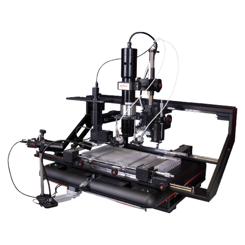
A top heater's wattage is not an acceptance test. The purchase decision is whether one installed rework system can remove, align, place and reflow the intended package on a representative board repeatedly, with measured temperatures and a documented inspection result.
Define the trial
Record the board and package before choosing a heater
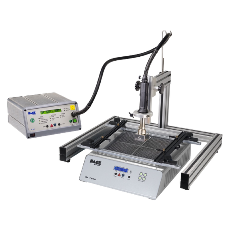
Specify board dimensions and thickness, thermal mass, nearby heat-sensitive parts, bottom-side clearance, package dimensions and the intended removal or installation task. List solder alloy, flux and the process owner's acceptance criteria. If the job requires optical alignment, state that explicitly: the ST925's handpiece and Z-axis stand should not be mistaken for a TF-series vision-placement station.
PACE lists a current ST925 bundle with an ST325 hot-air station, ST1600 infrared preheater and ST500A stand; older ST925 information shows a different preheater. Photograph the actual nameplates, nozzle and board holder rather than relying on a family image.
Measured process
Keep top and bottom temperatures, not just a recipe name
Place thermocouples on a representative board at the component and a sensitive nearby location, documenting attachment and calibration.
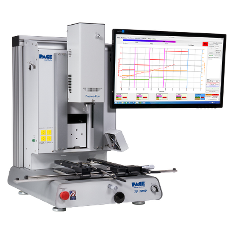
Record the top-heater, preheater and measured board curves through removal or installation; keep the machine program version and airflow/nozzle settings.
Compare peak temperature, time in the relevant reflow window and cooling behavior with the approved component, board and solder-material limits.
Repeat on more than one sample under the same documented setup, logging any rework, aborted cycle or changed setting rather than selecting only the best run.
Placement and inspection
Prove the result after the heating cycle
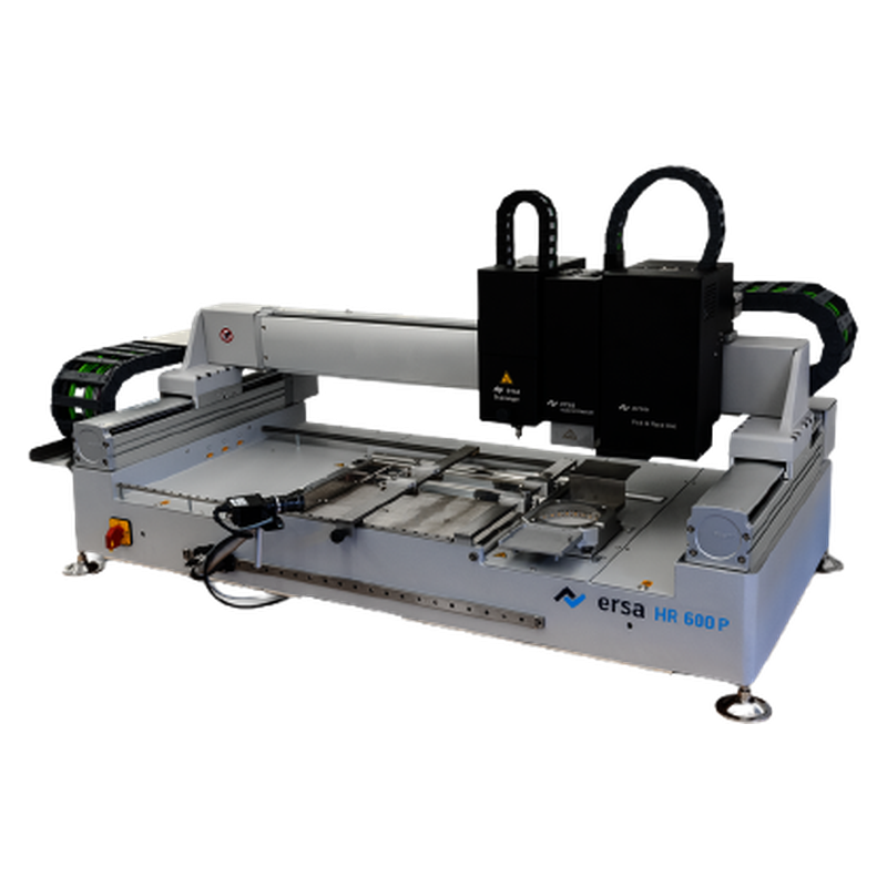
Document component and board alignment before placement, then inspect the assembly using the buyer's approved method. Keep images of the board before and after rework, visible pad or solder condition where possible, and a traceable defect or rework log. For hidden joints, agree whether X-ray or another validated method is needed. IPC-7711/21 addresses rework procedures and inspection in general; it does not make a brochure figure an acceptance test for this particular assembly.
For a vacuum reflow oven such as the Heller 1912MK5-VR, a vacuum trace and board-level void assessment are a different process proof. Do not treat oven-level vacuum data as evidence that a manual BGA rework station repeatedly aligns and places a component.
Acceptance pack
Request evidence that can be reviewed after the demonstration
- Model/serial photographs, installed heater, optics, board holder, nozzles, software version and calibration records.
- Representative board and package identity, solder/flux details, approved acceptance limits and trial setup photographs.
- Raw or exportable thermocouple traces and machine profiles for each trial, including failures and adjustments.
- Alignment captures where relevant, pre/post-inspection images, hidden-joint inspection results if required, and a disposition log.
- Running video of the actual unit that shows setup, removal or placement, heating, cooling and recorded output without presenting a reference clip as unit evidence.
Ask that each file be linked to the actual machine serial and board revision before packing or purchase approval.
Common mistakes
Avoid three shortcuts
- Comparing 575 W, 800 W or another headline heater figure without measuring the board's real thermal history.
- Approving a single successful demonstration while excluding failed cycles, configuration changes or alignment corrections.
- Assuming every unit carries the current manufacturer bundle, all optical options or the same software and board fixture.
Use the result carefully
What a repeat trial establishes
A documented repeat trial shows capability for the tested board, component lot, operator setup and installed machine state. It is not a blanket guarantee for other packages or future condition. Requalify when materials, nozzle, board revision, profile or machine configuration change.
Technical sources
PACE: current ST925 bundle and process controls